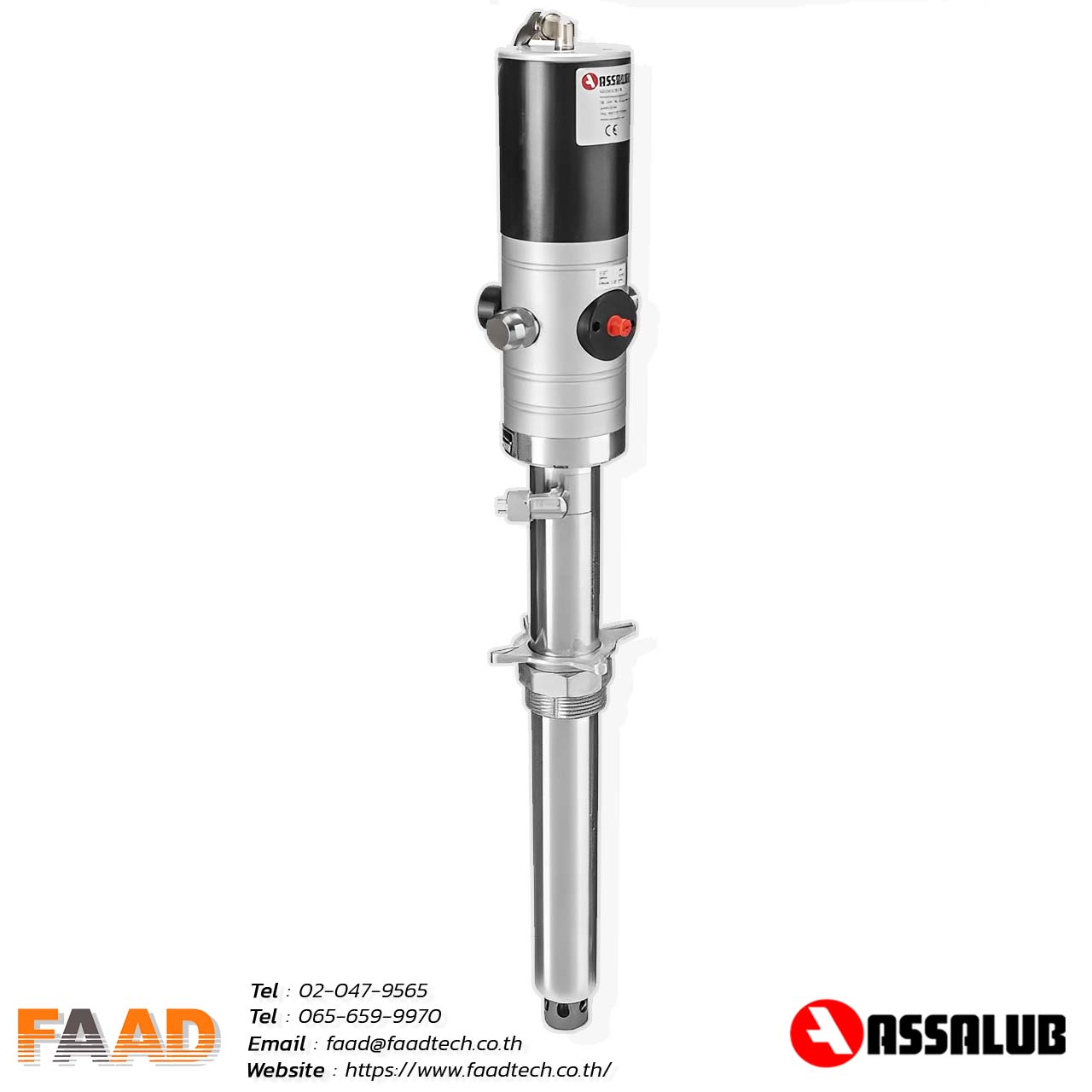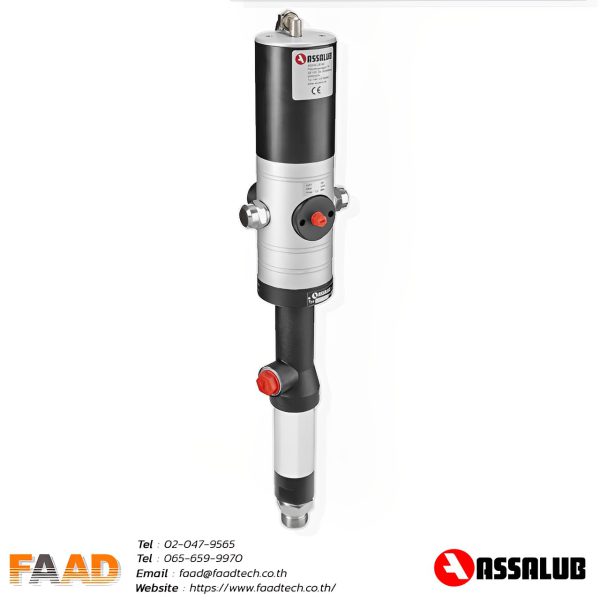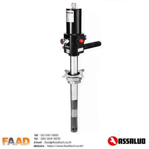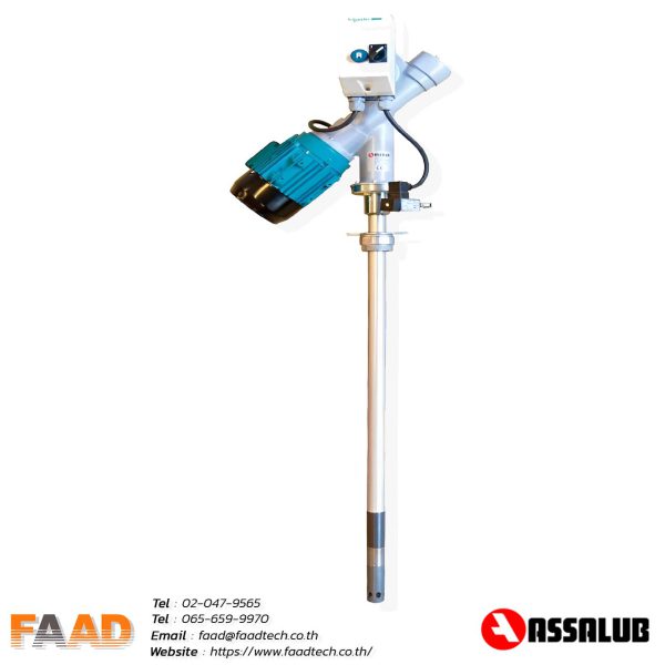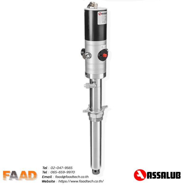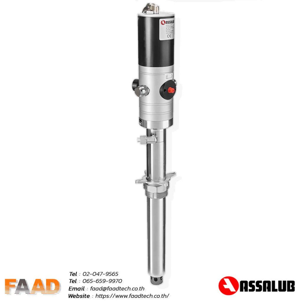
Grease pumps air operated rate 1:65
Part.nr: 0102093-0102095
| Grease pressure: | 7,500 psi |
| Capacity : | 1,200 g/min |
| Air connection: | ISO-G1/4 |
| Air pressure min-max: | 0,3-1,0 MPa/43-150 psi |
Technical info
It is virtually impossible to empty a grease drum completely by means of a conventional pump and follower plate. Our pumping innovation is the “Totally Empty Concept”. It challenges conventional construction because the pump is supported on a floating follower plate.
This follower plate/pump construction is designed as a completely closed grease handling system to empty a grease barrel. Only the grease remaining under the curved follower plate (circa 1.5-1.9 kg in a 180/200 kg drum) is left in the barrel.
Description
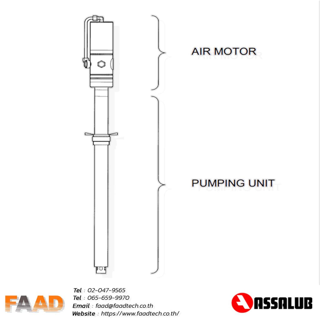
- The piston diameter of the air motor is 75 mm (~ 3”). The motor consists of an air
- cylinder with piston and one reciprocal valve. The valve directs the compressed air alternately to the top or bottom of the piston, thus producing a reciprocating motion ofthe air motor piston rod.
- The air motor is made of light alloy, stainless steel, brass, plastics and chromiumplated steel. It is thus highly resistant to rust caused by water in the compressed air.
- media pressure. When the pressure ratio is 1:65, we achieve a pressure of 9425 psi
- The compressed-air driven pumps are fully automatic. They start automatically when the media valve is opened and when the valve is closed they build up a back-pressure
and stop.
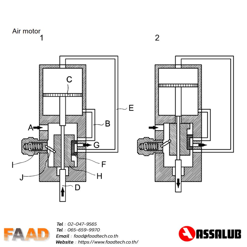
MODE OF OPERATION
When the piston moves upwards, see Figure 1:
Air enters at arrow A and passes through passage B to the underside of the piston C,driving the piston C and piston rod D upwards. The air above the piston is evacuated through passage E, past the valve slide F and out at arrow G.
The piston approaches top dead centre and the piston rod D makes contact with the slide driver H. When the slide driver H passes its mid position, the spring I and rocker J snap it over to its upper position, see Figure 2.
The incoming air is now led via passage E to the upper side of the piston C, driving it and the piston rod D downwards. The air under the piston C is evacuated through passage B, past the valve slide F and out at arrow G.
The piston approaches bottom dead centre and the piston rod D makes contact with the slide driver H. When the slide driver H passes it centre position, the spring I and rocker J snap it over to its lower position.
The air motor then repeats this cycle to produce a reciprocating motion, driven by compressed air.
Read Our Latest News
News & Articles
- By Admin Faadtech
- Comments are off for this post.
- By Admin Faadtech
- Comments are off for this post.


