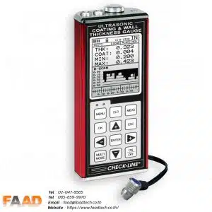
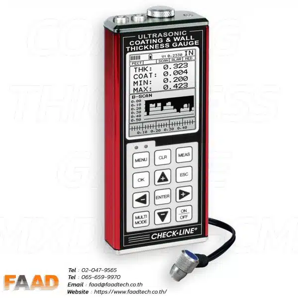
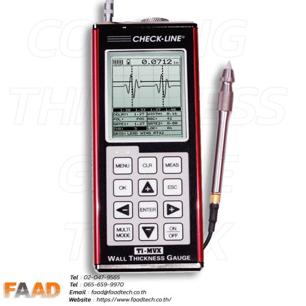
TI-25MXT Thru-Paint Ultrasonic Wall Thickness Gauge
The new CHECK-LINE TI-25MXT Wall Thickness Gauge accurately measures wall thickness and the extent of corrosion of all metals, ceramics, glass and most rigid plastics from one side. When operated in E-E Mode (Thru-Paint Mode), the coating is eliminated from the reading and the gauge will display only the thickness of the metal wall.
TI-25MXT Features include Automatic or Manual Probe Zero maximizing accuracy, 5-position Gain Adjustment to help located the correct backwall echo and to penetrate the walls on sound-attenuating materials such as cast metals and thick materials. It also features Differential mode, Hi-Low Alarms with audible and visual indicators and Scan mode that captures the minimum thickness at 100 measurements per second (100 Hz). It also includes a special Velocity Mode to measure in terms of velocity for nodularity testing.
The gauge and probe have a protection rating of IP67, is impact-resistant and environmentally sealed to provide trouble-free operation under the toughest field conditions The TI-25MXT can be used with any of the following hi-damped dual-element transducers specifically designed for use with E-E Thru-Paint Mode.
Measuring Range on Steel (with standard T-102-2700 probe)
Pulse-Echo (PE) Mode (Pit & Flaw Detection) – 0.040 to 8.00 inches / 1.00 to 199.9mm
Echo-Echo (EE) Mode (Through Paint & Coatings) – 0.100 to 1.000 inch / 2.54 to 25.40 mm
Total Measuring Range (Probe Dependant)
Pulse-Echo (PE) Mode (Pit & Flaw Detection) – 0.025 to 36.000 inches / 0.63 to 914.4 mm
Echo-Echo (EE) Mode (Through Paint & Coatings) – 0.100 to 1.000 inch / 2.54 to 25.40 mm
Features
- Includes NIST Traceable Calibration Certificate
- Includes both Pulse-Echo Mode (Pit & Flaw Detection) and Echo-Echo Mode (Through Paint & Coatings Mode)
- Using the standard probe T-102-2700, the gauge will read thru 0.040″ coating thickness (1 mm)
- Using one of the optional probes T-104-2700, the gauge will read thru 0.075″ coating thickness (1.9 mm)
- Calibrate to a sample of known thickness which automatically calculates the optimal acoustic velocity
- 2-Point Calibration to optimize linearity over a wide measurement range, automatically calculates the optimal acoustic velocity
- Scan mode, 100 readings/sec. Probe is slid over a large measuring area, the minimum thickness during the “scan” will be displayed
- Adjustable GAIN in 5 steps to fine tune the gauge for use on challenging materials or applications
- Differential mode, Hi-Low Alarms with audible and visual indicators
- User-selected Manual or Auto Zero of Transducer
- The extruded aluminum housing is impact-resistant and environmentally sealed (IP 65)
to provide trouble-free operation under the toughest field conditions - Special-purpose probes are offered for a variety of applications (1 to 10 MHz)
- Selectable Backlight ON/OFF/AUTO
- Resolution of 0.001 inch (0.01 mm)
Measuring Limits
| Minimum Radius for Convex Surfaces | 0.350″ (8.89 mm) |
| Minimum Radius for Concave Surfaces | 3″ (76.2 mm) |
| Minimum Headroom | 1″ (25.0 mm) |
| Minimum Sample Diameter | 0.150″ (3.8 mm) |
| Minimum Substrate Thickness – F | na |
| Minimum Substrate Thickness – NFe | na |
Specifications
| Range in Steel | Pulse-Echo Mode (Pit & Flaw Detection) measures from 0.025 to 19.999 inches (0.63 to 500 millimeters) Echo-Echo Mode (Through Paint & Coatings) measures from 0.100 to 1.000 inch (2.54 to 25.40 millimeters) (range depends upon probe selected) – five probes to choose from |
| Resolution | 0.001 inch (0.01 mm) |
| Velocity Range | 0.0120 to .7300 in/μs. 305 to 18,542 meters/sec |
| Probe (Standard) | 1/4″, 5 MHz Hi-Damp Dual Element Transducer, actual wearface is 5/8″ (17mm), p/n T-102-2700 |
| Probes (optional) | 1 to 10 MHz, 3/16″ up to 1 inch (custom probes available) |
| Probe Wearface | PEEK (Polyethylethylkytone) |
| Cable | 1.2m (4ft.) waterproof cable with non-polarized, quick-disconnect connectors |
| LCD Display | Multi-function 7 segment 4.5 digit liquid crystal display with 0.500″ digit height. Two 0.125 in14 segment fields for labels and values, and one 7 segment field for labels and values. Additional icons to indicate features and modes |
| Display Backlight | Backlight is selectable on/off/auto, and selectable brightness (Lo, Med, Hi) options |
| Display Update Rate | 10 Hz (10 updates/sec) |
| Temp. Limits | Ambient: -30 to 75° C (-22 to 167° F) Material: -20 to 100° C (0 to 200° F) High temperature probes available |
| Battery Type | 2x AA batteries (rechargeable batteries can be used) |
| Battery Life | 45 hours continuous use |
| Weight | 308 grams (11 ounces) |
| Dimensions | 63.5 x 131.3 x 31.5 mm (2.5″ x 5.17″ x 1.25″) |
| Accessories | Probe/cable assembly, 4 oz. bottle of coupling fluid, NIST Calibration Certificate, 2 AA batteries, operating instructions, hard-plastic carrying case. |
| Housing | Extruded aluminum body with nickel-plated aluminum end caps (gasket sealed) |
| Housing Rating | IP65 |
| Certifications | NIST Traceable and MIL-STD-45662A |
| Keypad | Sealed membrane that is resistant to both water and petroleum products Seven or eight tactile-feedback keys |
| Pulse Repetition Frequency (PRF) | 200 Hz (200 pulses/sec) |
| To Lock Settings | With gauge powered off, press and hold the “+” key while powering on the gauge The LOCK icon will be illuminated on the Display |
| To unLock Settings | With gauge powered off, press and hold the “-” key while powering on the gauge The LOCK icon will turn off |
| GAIN Adjustment | Adjustable GAIN 5-position (VLOW, LOW, MED, HIGH, VHI), in 3dB steps, 40-52dB |
| Time Dependent Gain (TDG) | Used in both pulse-echo (P-E) and Echo-Echo (E-E) modes depending on transducer and frequency selected |
| Measuring Mode | Pulse-Echo (P-E), Echo-Echo (E-E, Thru-Paint Mode), Scan, Differential, Alarm and VX-velocity |
| Pulser | 150 volt square wave pulser |











Read Our Latest News
News & Articles
- By Admin Faadtech
- Comments are off for this post.
- By Admin Faadtech
- Comments are off for this post.





![ฐาน Mounting แม่เหล็ก 2 ราง ขนาดเกลียว 1/4-28 [MH140-1A]](https://www.faadtech.co.th/wp-content/uploads/2024/05/CTC-MH136-1A-51-300x300.jpg.webp)
![ฐาน Mounting แม่เหล็ก 2 ราง ขนาดเกลียว 1/4-28 [MH140-1A] ฐาน Mounting แม่เหล็ก 2 ราง ขนาดเกลียว 1/4-28 [MH140-1A]](https://www.faadtech.co.th/wp-content/uploads/2024/05/MH140-1A-1-600x600.jpg.webp)
