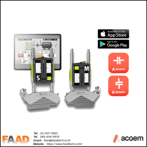
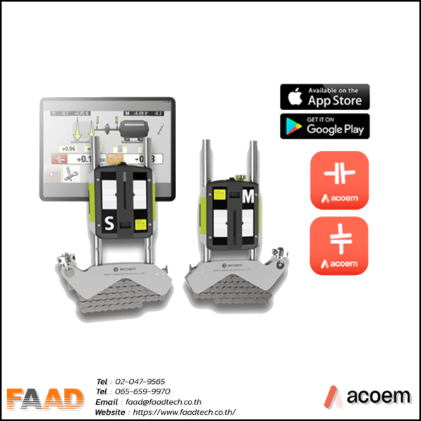
Laser Shaft Alingment AT-300
Laser Shaft Alignment AT300
ACOEM : Laser shaft alignment AT400
Laser shaft alignment AT300
- Extensive software functionality that offers advanced features and functionalities, boosting productivity and efficiency across multiple applications.
- Streamlined and user-friendly interface, meticulously designed to simplify navigation and elevate the overall
user experience. - Incorporation of intelligent sensor technology ensures swift and accurate results, enhancing performance and precision.
Powerful Sensor: Compatible with Laser Shaft alignment, reducing unnecessary energy consumption, extended measuring range, measuring up to 15m+-. State-of-the-art technology and high efficiency of ACOEM
Feature : Laser Shaft alignment AT 300
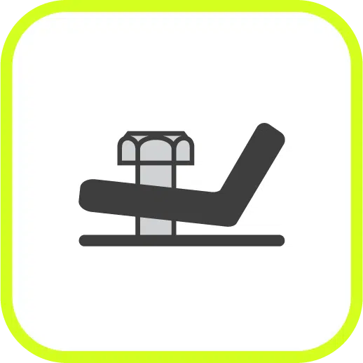
SoftCheck™
Easily verify the presence of soft foot with the SoftCheck™ feature to make a reliable alignment
Softfoot : is the state of the machine on all 4 sides are not at the same level caused by the legs or stands that are damaged or worn by use Come to learn more easily from the VDO clip.

Target values
Easily control the temperature of the machine. with cold and hot lines Target values

FeetLock™
Get better automatic guidance for a base-bound or bolt-bound situation with the FeetLock™ function

Spacer Shaft Function
The spacer shaft function is used when the alignment is performed on machinery using membrane coupling.

Multiple Feet
Some machines have more than two pairs of feet. To perform proper alignment in these cases, the Multiple Feet function comes handy
VertiZontal™
Align machines in horizontal and vertical direction in only one move with Acoem VertiZontal™ feature and save time
ACOEM : Laser shaft alignment AT400
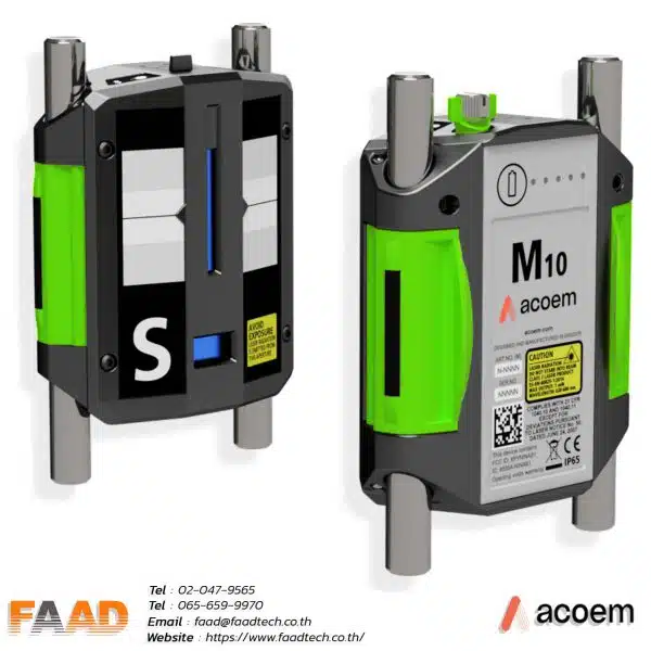
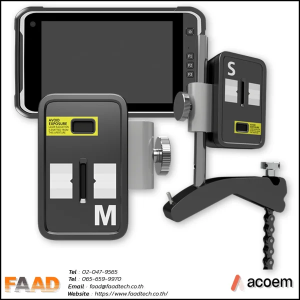
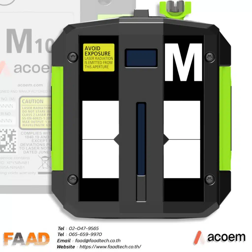
Sensors M10/S10 Gen III
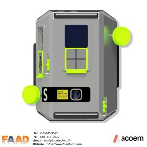
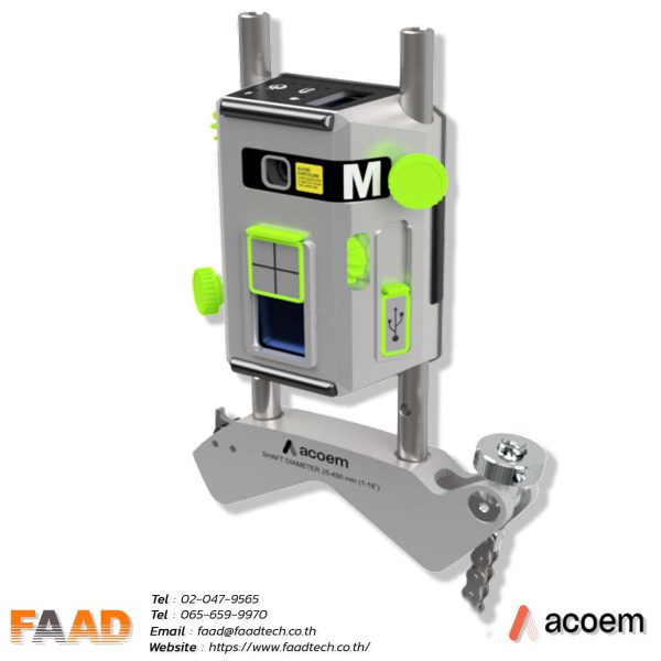
The M10/S10 sensors is a 3rd gen line sensor with a long measurement range of 15 meters for accurate distance detection.
The M10/S10 sensors now feature extensive software capabilities and reduced power consumption, offering improved performance.
Measuring methods.

Tripoint™ method
In the Tripoint method, the alignment condition can be calculated by taking three points while rotating the shaft at least 60°. In this method, all points are taken manually.

TRIPOINT Express™ method
This method seamlessly incorporates the Tripoint approach, offering the added advantage of fully automated measurements throughout the process.

Clock™ method
Clock™ In the Clock method, machinery positions are calculated by taking three points with 180° of rotation.

Multipoint method
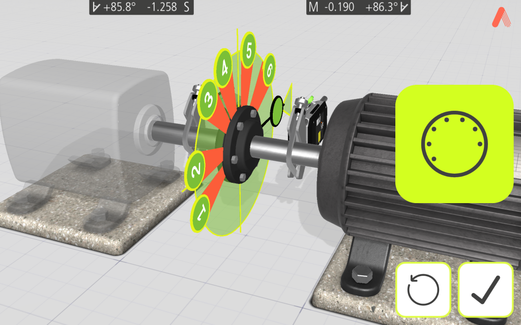
This function enables measurement initiation from any position on the rotation, allowing recording of multiple points for optimized calculations. Ideal for turbine and sliding bearing applications.
Multipoint Express method
Our method follows the classic Multipoint method approach, but with the advantage of automated measurements for greater convenience.

GuideU™,
Effortlessly navigate through our user-friendly interface, GuideU™, designed to make it a breeze to follow and understand.

True Live™
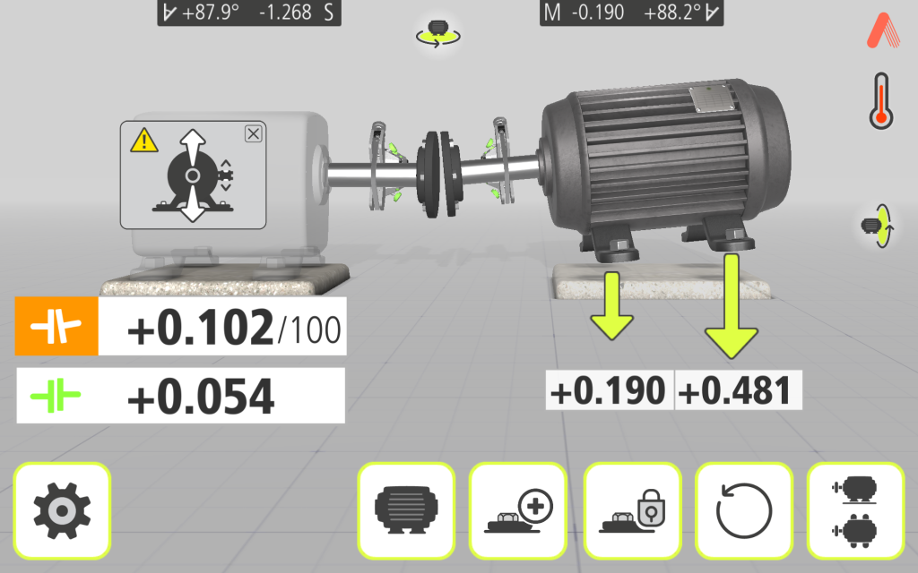
Get the position of both the shafts in real time with Acoem True Live™ feature

PDF EXPORT
Once the measurement is finished, you can generate a comprehensive PDF report that includes graphs and measurement data, providing detailed documentation of the measurement object.

Camera
Take pictures of your machines and setup to illustrate automatically in the report

Sync
Centralize and share your reports with your team, consolidate your plant’s alignment status, and assign alignment workorders to team members.
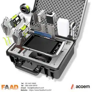
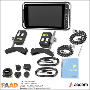
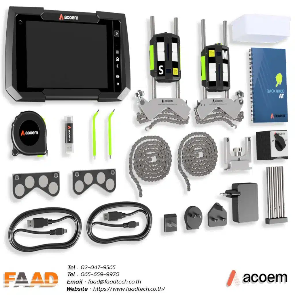
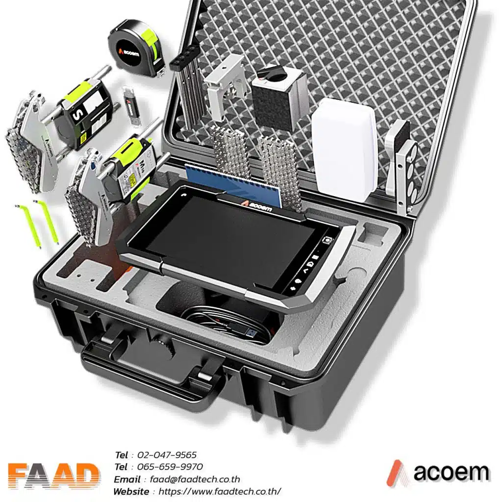
Packaging & Deliverables
Laser shaft alignment : AT-300
• Acoem Alignment Display
• Acoem M10
• Acoem S10
• Magnetic base ON-OFF
• Extension fixture 49mm
• Rod kit
• Chain 8 mm 60 links (L=970 mm)
• Magnetic v-bracket
• Tape measure 5 m with label
• V-bracket complete
• Angled universal tool
• Acoem USB
• Spacer magnet v-brackets
• USB-cable A-mini B 2m
• Power supply 4 USB-ports 5 VDC
• Quick Guide AT











Read Our Latest News
News & Articles
- By Admin Faadtech
- Comments are off for this post.
- By Admin Faadtech
- Comments are off for this post.


